SPO600 Software Portability & Optimization Lab02
Hello and welcome to the second installment of this blog. In this blog we will be reviewing my attempt at Lab 02 for my SPO600 class. In this lab we are required to create our own 6502 assembly application. For this I have chosen to do a resistor calculator. I chose this because prior to coming into CPA I was enrolled in ETC (Computer Engineering Technology) where they taught us about electricity, resistors, and creating circuits. It is a good way for me to familiarize myself again with resistors and the math behind them.
The problem
We want to be able to take in the color bands that are on the resistor and quickly calculate their resistance in a measurement of ohms. To accomplish this we would required to take the user input for the color of the bands, our application will support 4 band resistors currently, and will not be able to identify any resistor with 5 bands.
The code
The code can be viewed at my Github page located here. I will not be posting the entire code here as it has a lot of boilerplate setup but I will however be breaking down parts of the code that are relevant for the process of calculating and displaying the resistor on screen.
The breakdown
To start I decided to draw out the shape of a resistor on the bitmap.

This was accomplished by drawing out a shape in excel with the provided bitmapped screen memory map located here. After drawing the shape out I copied all the selected address's and with a little bit of VSCode keyboard shortcuts, I was able to put them into a loop and color them in with cyan.
After this point I needed to display the color codes to the user so they could select the colors of the resistor bands, and I needed to take input from the user.
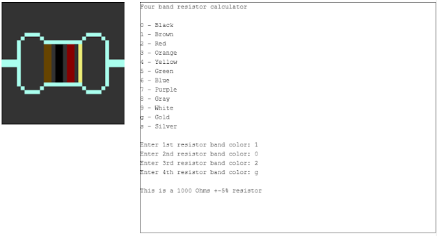
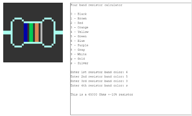
This is what the result looks like:


Here we are using the print method provided by Professor Chris Tyler from his wordle assembly game to display the color codes and their color name and asking the user for input. We then store the input's from memory location $01 - $04 to be used later.

As we receive inputs from the user, we draw out the resistor bands in real-time and continuously ask the user for input for all four bands.


Another issue i had was figuring out how to display the correct number of zero's for the multiplier. This was solved by loading the value stored in the memory location for the multiplier ($03) and storing that value in the Y register, and running a loop while decrementing Y.

Here we see that $03 holds the value 02, which should only print two zeroes for the red multiplier, thus making this a 1000 (1k) ohm resistor.

Comments
Post a Comment